Hyper-V Network Virtualization Technical Details in Windows Server
Applies to: Windows Server 2022, Windows Server 2019, Windows Server 2016, Azure Stack HCI, versions 21H2 and 20H2
Server virtualization enables multiple server instances to run concurrently on a single physical host; yet server instances are isolated from each other. Each virtual machine essentially operates as if it is the only server running on the physical computer.
Network virtualization provides a similar capability, in which multiple virtual networks (potentially with overlapping IP addresses) run on the same physical network infrastructure and each virtual network operates as if it is the only virtual network running on the shared network infrastructure. Figure 1 shows this relationship.
Figure 1: Server virtualization versus network virtualization
Hyper-V Network Virtualization Concepts
In Hyper-V Network Virtualization (HNV), a customer or tenant is defined as the "owner" of a set of IP subnets that are deployed in an enterprise or datacenter. A customer can be a corporation or enterprise with multiple departments or business units in a private datacenter which require network isolation, or a tenant in a public data center which is hosted by a service provider. Each customer can have one or more Virtual networks in the datacenter, and each virtual network consists of one or more Virtual subnets.
There are two HNV implementations which will be available in Windows Server 2016: HNVv1 and HNVv2.
HNVv1
HNVv1 is compatible with Windows Server 2012 R2 and System Center 2012 R2 Virtual Machine Manager (VMM). Configuration for HNVv1 relies on WMI management and Windows PowerShell cmdlets (facilitated through System Center VMM) to define isolation settings and Customer Address (CA) - virtual network - to Physical Address (PA) mappings and routing. No additional features have been added to HNVv1 in Windows Server 2016 and no new features are planned.
- SET Teaming and HNV V1 are not compatible by platform.
o To use HA NVGRE gateways users need to either use LBFO team or No team. Or
o Use Network Controller Deployed gateways with SET teamed switch.
HNVv2
A significant number of new features are included in HNVv2 which is implemented using the Azure Virtual Filtering Platform (VFP) forwarding extension in the Hyper-V Switch. HNVv2 is fully integrated with Microsoft Azure Stack which includes the new Network Controller in the Software Defined Networking (SDN) Stack. Virtual network policy is defined through the Microsoft Network Controller using a RESTful NorthBound (NB) API and plumbed to a Host Agent via multiple SouthBound Interfaces (SBI) including OVSDB. The Host Agent programs policy in the VFP extension of the Hyper-V Switch where it is enforced.
Important
This topic focuses on HNVv2.
Virtual network
Each virtual network consists of one or more virtual subnets. A virtual network forms an isolation boundary where the virtual machines within a virtual network can only communicate with each other. Traditionally, this isolation was enforced using VLANs with a segregated IP address range and 802.1q Tag or VLAN ID. But with HNV, isolation is enforced using either NVGRE or VXLAN encapsulation to create overlay networks with the possibility of overlapping IP subnets between customers or tenants.
Each virtual network has a unique Routing Domain ID (RDID) on the host. This RDID roughly maps to a Resource ID to identify the virtual network REST resource in the Network Controller. The virtual network REST resource is referenced using a Uniform Resource Identifier (URI) namespace with the appended Resource ID.
Virtual subnets
A virtual subnet implements the Layer 3 IP subnet semantics for the virtual machines in the same virtual subnet. The virtual subnet forms a broadcast domain (similar to a VLAN) and isolation is enforced by using either the NVGRE Tenant Network ID (TNI) or VXLAN Network Identifier (VNI) field.
Each virtual subnet belongs to a single virtual network (RDID), and it is assigned a unique Virtual Subnet ID (VSID) using either the TNI or VNI key in the encapsulated packet header. The VSID must be unique within the datacenter and is in the range 4096 to 2^24-2.
A key advantage of the virtual network and routing domain is that it allows customers to bring their own network topologies (for example, IP subnets) to the cloud. Figure 2 shows an example where the Contoso Corp has two separate networks, the R&D Net and the Sales Net. Because these networks have different routing domain IDs, they cannot interact with each other. That is, Contoso R&D Net is isolated from Contoso Sales Net even though both are owned by Contoso Corp. Contoso R&D Net contains three virtual subnets. Note that both the RDID and VSID are unique within a datacenter.
Figure 2: Customer networks and virtual subnets
Layer 2 Forwarding
In Figure 2, the virtual machines in VSID 5001 can have their packets forwarded to virtual machines that are also in VSID 5001 through the Hyper-V Switch. The incoming packets from a virtual machine in VSID 5001 are sent to a specific VPort on the Hyper-V Switch. Ingress rules (for example encap) and mappings (for example encapsulation header) are applied by the Hyper-V Switch for these packets. The packets are then forwarded either to a different VPort on the Hyper-V Switch (if the destination virtual machine is attached to the same host) or to a different Hyper-V switch on a different host (if the destination virtual machine is located on a different host).
Layer 3 Routing
Similarly, the virtual machines in VSID 5001 can have their packets routed to virtual machines in VSID 5002 or VSID 5003 by the HNV distributed router which is present in each Hyper-V host's VSwitch. Upon delivering the packet to the Hyper-V switch, HNV updates the VSID of the incoming packet to the VSID of the destination virtual machine. This will only happen if both VSIDs are in the same RDID. Therefore, virtual network adapters with RDID1 cannot send packets to virtual network adapters with RDID2 without traversing a gateway.
Note
In the packet flow description above, the term "virtual machine" actually means the virtual network adapter on the virtual machine. The common case is that a virtual machine only has a single virtual network adapter. In this case, the words "virtual machine" and "virtual network adapter" can conceptually mean the same thing.
Each virtual subnet defines a Layer 3 IP subnet and a Layer 2 (L2) broadcast domain boundary similar to a VLAN. When a virtual machine broadcasts a packet, HNV uses Unicast Replication (UR) to make a copy of the original packet and replace the destination IP and MAC with the addresses of each VM which are in the same VSID.
Note
When Windows Server 2016 ships, broadcast and subnet multicasts will be implemented using unicast replication. Cross-subnet multicast routing and IGMP are not supported.
In addition to being a broadcast domain, the VSID provides isolation. A virtual network adapter in HNV is connected to a Hyper-V switch port that will have ACL rules applied either directly to the port (virtualNetworkInterface REST resource) or to the virtual subnet (VSID) of which it is a part.
The Hyper-V switch port must have an ACL rule applied. This ACL could be ALLOW ALL, DENY ALL, or be more specific to only allow certain types of traffic based on 5-tuple (Source IP, Destination IP, Source Port, Destination Port, Protocol) matching.
Note
Hyper-V Switch Extensions will not work with HNVv2 in the new Software Defined Networking (SDN) stack. HNVv2 is implemented using the Azure Virtual Filtering Platform (VFP) switch extension which cannot be used in conjunction with any other 3rd-party switch extension.
Switching and Routing in Hyper-V Network Virtualization
HNVv2 implements correct Layer 2 (L2) switching and Layer 3 (L3) routing semantics to work just as a physical switch or router would work. When a virtual machine connected to an HNV virtual network attempts to establish a connection with another virtual machine in the same virtual subnet (VSID) it will first need to learn the CA MAC address of the remote virtual machine. If there is an ARP entry for the destination virtual machine's IP address in the source virtual machine's ARP table, the MAC address from this entry is used. If an entry does not exist, the source virtual machine will send an ARP broadcast with a request for the MAC address corresponding to the destination virtual machine's IP address to be returned. The Hyper-V Switch will intercept this request and send it to the Host Agent. The Host Agent will look in its local database for a corresponding MAC address for the requested destination virtual machine's IP address.
Note
The Host Agent, acting as the OVSDB server, uses a variant of the VTEP schema to store CA-PA mappings, MAC table, and so on.
If a MAC address is available, the Host Agent injects an ARP response and sends this back to the virtual machine. After the virtual machine's networking stack has all the required L2 header information, the frame is sent to the corresponding Hyper-V Port on the V-Switch. Internally, the Hyper-V Switch tests this frame against N-tuple matching rules assigned to the V-Port and applies certain transformations to the frame based on these rules. Most importantly, a set of encapsulation transformations is applied to construct the encapsulation header using either NVGRE or VXLAN, depending on the policy defined at the Network Controller. Based on the policy programmed by the Host Agent, a CA-PA mapping is used to determine the IP address of the Hyper-V host where the destination virtual machine resides. The Hyper-V Switch ensures the correct routing rules and VLAN tags are applied to the outer packet so it reaches the remote PA address.
If a virtual machine connected to an HNV virtual network wants to create a connection with a virtual machine in a different virtual subnet (VSID), the packet needs to be routed accordingly. HNV assumes a star-topology where there is only one IP address in the CA space used as the next-hop to reach all IP prefixes (meaning one default route/gateway). Currently, this enforces a limitation to a single default route and non-default routes are not supported.
Routing Between Virtual Subnets
In a physical network, an IP subnet is a Layer 2 (L2) domain where computers (virtual and physical) can directly communicate with each other. The L2 domain is a broadcast domain where ARP entries (IP:MAC address map) are learned through ARP requests that are broadcast on all interfaces and ARP responses are sent back to the requesting host. The computer uses the MAC information learned from the ARP response to completely construct the L2 frame including Ethernet headers. However, if an IP address is in a different L3 subnet, the ARP request does not cross this L3 boundary. Instead, an L3 router interface (next-hop or default gateway) with an IP address in the source subnet must respond to these ARP requests with its own MAC address.
In standard Windows networking, an administrator can create static routes and assign these to a network interface. Additionally, a "default gateway" is usually configured to be the next-hop IP address on an interface where packets destined for the default route (0.0.0.0/0) are sent. Packets are sent to this default gateway if no specific routes exist. This is typically the router for your physical network. HNV uses a built-in router that is part of every host and has an interface in every VSID to create a distributed router for the virtual network(s).
Since HNV assumes a star topology, the HNV distributed router acts as a single default gateway for all traffic that is going between Virtual Subnets that are part of the same VSID network. The address used as the default gateway defaults to the lowest IP address in the VSID and is assigned to the HNV distributed router. This distributed router allows for a very efficient way for all traffic inside a VSID Network to be routed appropriately because each host can directly route the traffic to the appropriate host without needing an intermediary. This is particularly true when two virtual machines in the same VM Network but different Virtual Subnets are on the same physical host. As you will see later in this section, the packet never has to leave the physical host.
Routing between PA subnets
In contrast to HNVv1 which allocated one PA IP address for each Virtual Subnet (VSID), HNVv2 now uses one PA IP address per Switch-Embedded Teaming (SET) NIC team member. The default deployment assumes a two-NIC team and assigns two PA IP addresses per host. A single host has PA IPs assigned from the same Provider (PA) logical subnet on the same VLAN. Two tenant VMs in the same virtual subnet may indeed be located on two different hosts which are connected to two different provider logical subnets. HNV will construct the outer IP headers for the encapsulated packet based on the CA-PA mapping. However, it relies on the host TCP/IP stack to ARP for the default PA gateway and then builds the outer Ethernet headers based on the ARP response. Typically, this ARP response comes from the SVI interface on the physical switch or L3 router where the host is connected. HNV therefore relies on the L3 router for routing the encapsulated packets between provider logical subnets / VLANs.
Routing Outside a Virtual Network
Most customer deployments will require communication from the HNV environment to resources that are not part of the HNV environment. Network Virtualization gateways are required to allow communication between the two environments. Infrastructures requiring an HNV Gateway include Private Cloud and Hybrid Cloud. Basically, HNV gateways are required for Layer 3 routing between internal and external (physical) networks (including NAT) or between different sites and/or clouds (private or public) which use an IPSec VPN or GRE tunnel.
Gateways can come in different physical form factors. They can be built on Windows Server 2016, incorporated into a Top of Rack (TOR) switch acting as a VXLAN Gateway, accessed through a Virtual IP (VIP) advertised by a load balancer, put into other existing network appliances, or can be a new stand-alone network appliance.
For more information about Windows RAS Gateway options, see RAS Gateway.
Packet Encapsulation
Each virtual network adapter in HNV is associated with two IP addresses:
Customer Address (CA) The IP address assigned by the customer, based on their intranet infrastructure. This address allows the customer to exchange network traffic with the virtual machine as if it had not been moved to a public or private cloud. The CA is visible to the virtual machine and reachable by the customer.
Provider Address (PA) The IP address assigned by the hosting provider or the datacenter administrators based on their physical network infrastructure. The PA appears in the packets on the network that are exchanged with the server running Hyper-V that is hosting the virtual machine. The PA is visible on the physical network, but not to the virtual machine.
The CAs maintain the customer's network topology, which is virtualized and decoupled from the actual underlying physical network topology and addresses, as implemented by the PAs. The following diagram shows the conceptual relationship between virtual machine CAs and network infrastructure PAs as a result of network virtualization.
Figure 6: Conceptual diagram of network virtualization over physical infrastructure
In the diagram, customer virtual machines are sending data packets in the CA space, which traverse the physical network infrastructure through their own virtual networks, or "tunnels". In the example above, the tunnels can be thought of as "envelopes" around the Contoso and Fabrikam data packets with green shipping labels (PA addresses) to be delivered from the source host on the left to the destination host on the right. The key is how the hosts determine the "shipping addresses" (PA's) corresponding to the Contoso and the Fabrikam CA's, how the "envelope" is put around the packets, and how the destination hosts can unwrap the packets and deliver to the Contoso and Fabrikam destination virtual machines correctly.
This simple analogy highlighted the key aspects of network virtualization:
Each virtual machine CA is mapped to a physical host PA. There can be multiple CAs associated with the same PA.
Virtual machines send data packets in the CA spaces, which are put into an "envelope" with a PA source and destination pair based on the mapping.
The CA-PA mappings must allow the hosts to differentiate packets for different customer virtual machines.
As a result, the mechanism to virtualize the network is to virtualize the network addresses used by the virtual machines. The network controller is responsible for the address mapping, and the host agent maintains the mapping database using the MS_VTEP schema. The next section describes the actual mechanism of address virtualization.
Network virtualization through address virtualization
HNV implements overlay tenant networks using either Network Virtualization Generic Routing Encapsulation (NVGRE) or the Virtual eXtensible Local Area Network (VXLAN). VXLAN is the default.
Virtual eXtensible Local Area Network (VXLAN)
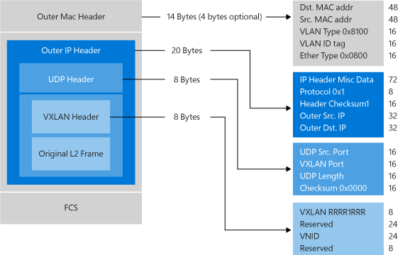
The Virtual eXtensible Local Area Network (VXLAN) (RFC 7348) protocol has been widely adopted in the market place, with support from vendors like Cisco, Brocade, Arista, Dell, HP and others. The VXLAN protocol uses UDP as the transport. The IANA-assigned UDP destination port for VXLAN is 4789 and the UDP source port should be a hash of information from the inner packet to be used for ECMP spreading. After the UDP header, a VXLAN header is appended to the packet which includes a reserved 4-byte field followed by a 3-byte field for the VXLAN Network Identifier (VNI) - VSID - followed by another reserved 1-byte field. After the VXLAN header, the original CA L2 frame (without the CA Ethernet frame FCS) is appended.
Generic Routing Encapsulation (NVGRE)
This network virtualization mechanism uses the Generic Routing Encapsulation (NVGRE) as part of the tunnel header. In NVGRE, the virtual machine's packet is encapsulated inside another packet. The header of this new packet has the appropriate source and destination PA IP addresses in addition to the Virtual Subnet ID, which is stored in the Key field of the GRE header, as shown in Figure 7.
Figure 7: Network virtualization - NVGRE encapsulation
The Virtual Subnet ID allows hosts to identify the customer virtual machine for any given packet, even though the PA's and the CA's on the packets may overlap. This allows all virtual machines on the same host to share a single PA, as shown in Figure 7.
Sharing the PA has a big impact on network scalability. The number of IP and MAC addresses that need to be learned by the network infrastructure can be substantially reduced. For instance, if every end host has an average of 30 virtual machines, the number of IP and MAC addresses that need to be learned by the networking infrastructure is reduced by a factor of 30.The embedded Virtual Subnet IDs in the packets also enable easy correlation of packets to the actual customers.
The PA sharing scheme for Windows Server 2012 R2 is one PA per VSID per host. For Windows Server 2016 the scheme is one PA per NIC team member.
With Windows Server 2016 and later, HNV fully supports NVGRE and VXLAN out of the box; it does NOT require upgrading or purchasing new network hardware such as NICs (network adapters), switches, or routers. This is because these packets on the wire are regular IP packet in the PA space, which is compatible with today's network infrastructure. However, to get the best performance use supported NICs with the latest drivers that support task offloads.
Multi-tenant deployment example
The following diagram shows an example deployment of two customers located in a cloud datacenter with the CA-PA relationship defined by the network policies.
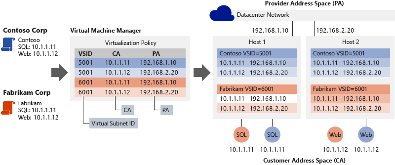
Figure 8: Multi-tenant deployment example
Consider the example in Figure 8. Prior to moving to the hosting provider's shared IaaS service:
Contoso Corp ran a SQL Server (named SQL) at the IP address 10.1.1.11 and a web server (named Web) at the IP address 10.1.1.12, which uses its SQL Server for database transactions.
Fabrikam Corp ran a SQL Server, also named SQL and assigned the IP address 10.1.1.11, and a web server, also named Web and also at the IP address 10.1.1.12, that uses its SQL Server for database transactions.
We will assume that the hosting service provider has previously created the provider (PA) logical network through the Network Controller to correspond to their physical network topology. The Network Controller allocates two PA IP addresses from the logical subnet's IP prefix where the hosts are connected. The network controller also indicates the appropriate VLAN tag to apply the IP addresses.
Using the Network Controller, Contoso Corp and Fabrikam Corp then create their virtual network and subnets which are backed by the provider (PA) logical network specified by the hosting service provider. Contoso Corp and Fabrikam Corp move their respective SQL Servers and web servers to the same hosting provider's shared IaaS service where, coincidentally, they run the SQL virtual machines on Hyper-V Host 1 and the Web (IIS7) virtual machines on Hyper-V Host 2. All virtual machines maintain their original intranet IP addresses (their CAs).
Both companies are assigned the following Virtual Subnet ID (VSID) by the Network Controller as indicated below. The Host Agent on each of the Hyper-V hosts receives the allocated PA IP addresses from the Network Controller and creates two PA host vNICs in a non-default network compartment. A network interface is assigned to each of these host vNICs where the PA IP address is assigned as shown below:
Contoso Corp's virtual machines VSID and PAs : VSID is 5001, SQL PA is 192.168.1.10, Web PA is 192.168.2.20
Fabrikam Corp's virtual machines VSID and PAs: VSID is 6001, SQL PA is 192.168.1.10, Web PA is 192.168.2.20
The Network Controller plumbs all network policy (including CA-PA mapping) to the SDN Host Agent which will maintain the policy in a persistent store (in OVSDB database tables).
When the Contoso Corp Web virtual machine (10.1.1.12) on Hyper-V Host 2 creates a TCP connection to the SQL Server at 10.1.1.11, the following happens:
VM ARPs for the destination MAC address of 10.1.1.11
The VFP extension in the vSwitch intercepts this packet and sends it to the SDN Host Agent
The SDN Host Agent looks in its policy store for the MAC address for 10.1.1.11
If a MAC is found, the Host Agent injects an ARP response back to the VM
If a MAC is not found, no response is sent and the ARP entry in the VM for 10.1.1.11 is marked unreachable.
The VM now constructs a TCP packet with the correct CA Ethernet and IP headers and sends it to the vSwitch
The VFP forwarding extension in the vSwitch processes this packet through the VFP layers (described below) assigned to the source vSwitch port on which the packet was received and creates a new flow-entry in the VFP unified flow table
The VFP engine performs rule matching or flow-table lookup for each layer (for example virtual network layer) based on the IP and Ethernet headers.
The matched rule in the virtual network layer references a CA-PA mapping space and performs encapsulation.
The encapsulation type (either VXLAN or NVGRE) is specified in the VNet layer along with the VSID.
In the case of VXLAN encapsulation, an outer UDP header is constructed with the VSID of 5001 in the VXLAN header. An outer IP header is constructed with the source and destination PA address assigned to the Hyper-V Host 2 (192.168.2.20) and Hyper-V Host 1 (192.168.1.10) respectively based on the SDN Host Agent's policy store.
This packet then flows to the PA routing layer in VFP.
The PA routing layer in VFP will reference the network compartment used for PA-space traffic and a VLAN ID and use the TCP/IP stack of the host to forward the PA packet to Hyper-V Host 1 correctly.
Upon receipt of the encapsulated packet, Hyper-V Host 1 receives the packet in the PA network compartment and forward it to the vSwitch.
The VFP processes the packet through its VFP layers and create a new flow-entry in the VFP unified flow table.
The VFP engine matches the ingress rules in the virtual network layer and strips off the outer encapsulated packet's Ethernet, IP, and VXLAN headers.
The VFP engine then forwards the packet to the vSwitch port to which the destination VM is connected.
A similar process for traffic between the Fabrikam Corp Web and SQL virtual machines uses the HNV policy settings for the Fabrikam Corp. As a result, with HNV, Fabrikam Corp and Contoso Corp virtual machines interact as if they were on their original intranets. They can never interact with each other, even though they are using the same IP addresses.
The separate addresses (CAs and PAs), the policy settings of the Hyper-V hosts, and the address translation between the CA and the PA for inbound and outbound virtual machine traffic isolate these sets of servers using either the NVGRE Key or the VLXAN VNID. Furthermore, the virtualization mappings and transformation decouples the virtual network architecture from the physical network infrastructure. Although Contoso SQL and Web and Fabrikam SQL and Web reside in their own CA IP subnets (10.1.1/24), their physical deployment happens on two hosts in different PA subnets, 192.168.1/24 and 192.168.2/24, respectively. The implication is that cross-subnet virtual machine provisioning and live migration become possible with HNV.
Hyper-V Network Virtualization architecture
In Windows Server 2016, HNVv2 is implemented using the Azure Virtual Filtering Platform (VFP) which is an NDIS filtering extension within the Hyper-V Switch. The key concept of VFP is that of a Match-Action flow engine with an internal API exposed to the SDN Host Agent for programming network policy. The SDN Host Agent itself receives network policy from the Network Controller over the OVSDB and WCF SouthBound communication channels. Not only is virtual network policy (for example CA-PA mapping) programmed using VFP but additional policy such as ACLs, QoS, and so on.
The object hierarchy for the vSwitch and VFP forwarding extension is the following:
vSwitch
External NIC Management
NIC Hardware Offloads
Global Forwarding rules
Port
Egress forwarding layer for hair-pinning
Space lists for mappings and NAT pools
Unified Flow Table
VFP Layer
Flow table
Group
Rule
- Rules can reference spaces
In the VFP, a layer is created per policy type (for example, Virtual Network) and is a generic set of rule/flow tables. It does not have any intrinsic functionality until specific rules are assigned to that layer to implement such functionality. Each layer is assigned a priority and layers are assigned to a port by ascending priority. Rules are organized into groups based primarily on direction and IP address family. Groups are also assigned a priority and at most, one rule from a group can match a given flow.
The forwarding logic for the vSwitch with VFP extension is as follows:
Ingress processing (ingress from the point of view of packet coming into a port)
Forwarding
Egress processing (egress from the point of view of packet leaving a port)
The VFP supports inner MAC forwarding for NVGRE and VXLAN encapsulation types as well as outer MAC VLAN based forwarding.
The VFP extension has a slow-path and fast-path for packet traversal. The first packet in a flow must traverse all rule groups in each layer and do a rule lookup which is an expensive operation. However, once a flow is registered in the unified flow table with a list of actions (based on the rules matched) all subsequent packets will be processed based on the unified flow table entries.
HNV policy is programmed by the host agent. Each virtual machine network adapter is configured with an IPv4 address. These are the CAs that will be used by the virtual machines to communicate with each other, and they are carried in the IP packets from the virtual machines. HNV encapsulates the CA frame in a PA frame based on the network virtualization policies stored in the host agent's database.
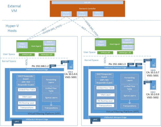
Figure 9: HNV Architecture
Summary
Cloud-based datacenters can provide many benefits such as improved scalability and better resource utilization. To realize these potential benefits requires a technology that fundamentally addresses the issues of multi-tenant scalability in a dynamic environment. HNV was designed to address these issues and also improve the operational efficiency of the datacenter by decoupling the virtual network topology for the physical network topology. Building on an existing standard, HNV runs in today's datacenter and operates with your existing VXLAN infrastructure. Customers with HNV can now consolidate their datacenters into a private cloud or seamlessly extend their datacenters to a hosting server provider's environment with a hybrid cloud.
See also
To learn more about HNVv2 see the following links:
| Content type | References |
|---|---|
| Community Resources | - Private Cloud Architecture Blog - Ask questions: cloudnetfb@microsoft.com |
| RFC | - NVGRE Draft RFC - VXLAN - RFC 7348 |
| Related Technologies | - For Hyper-V Network Virtualization technical details in Windows Server 2012 R2 , see Hyper-V Network Virtualization technical details - Network Controller |
Feedback
Coming soon: Throughout 2024 we will be phasing out GitHub Issues as the feedback mechanism for content and replacing it with a new feedback system. For more information see: https://aka.ms/ContentUserFeedback.
Submit and view feedback for